Inkscape Tutorial: Customizing your document properties on Inkscape

Summary​

1. Laser Cutting with Inkscape: Customizing your Document Properties on Inkscape

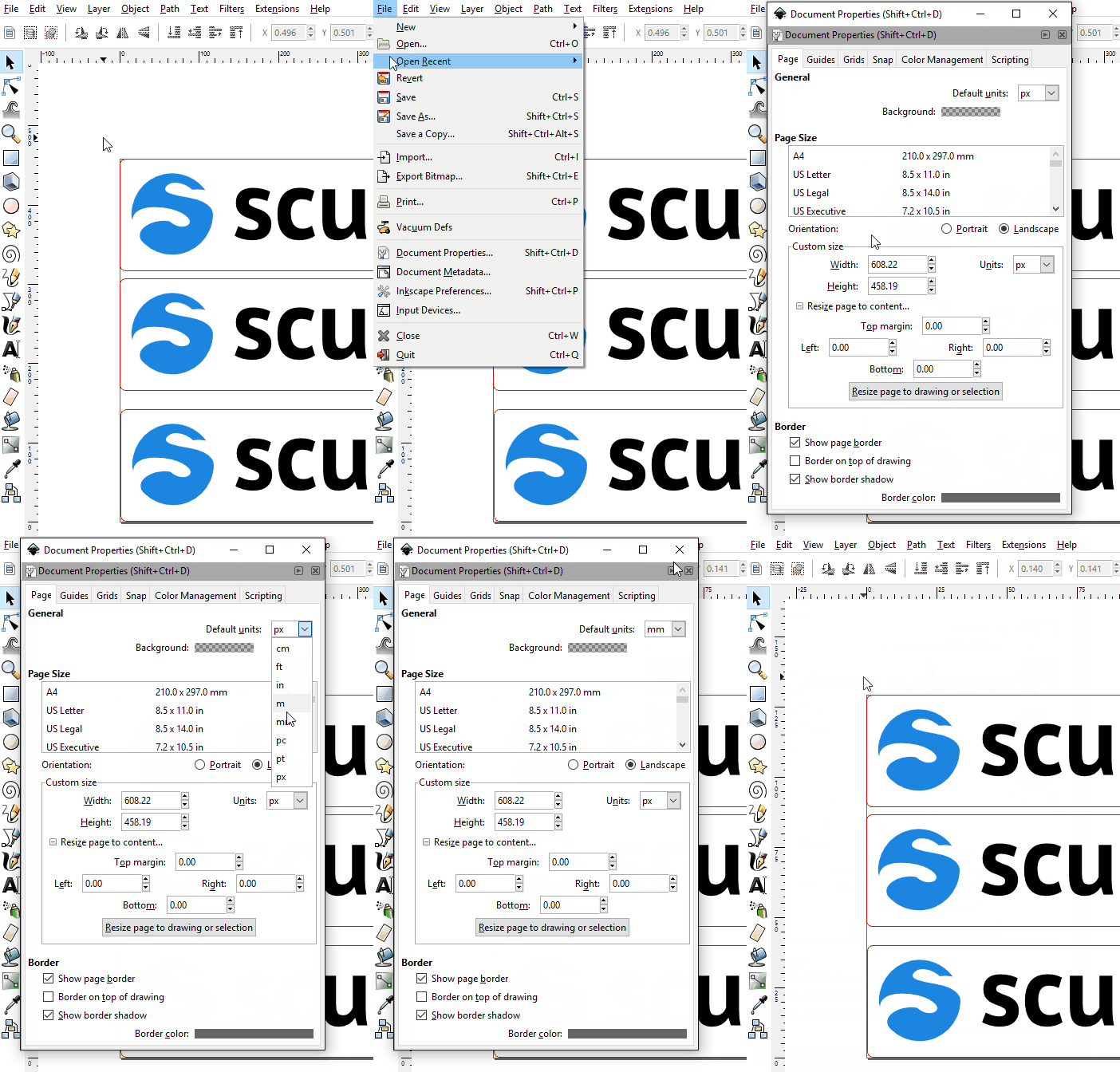
Units Laser Cutting Inkscape.gif 

The first step is to open up Document Properties (File -> Document Properties). Here in the “General” section for the “Page” tab you’ll see that you can set the “Default units”. For our purposes, set this to “mm”. This will set Inkscape’s rulers to use millimetres instead of pixels, which makes checking things and using guides much easier.

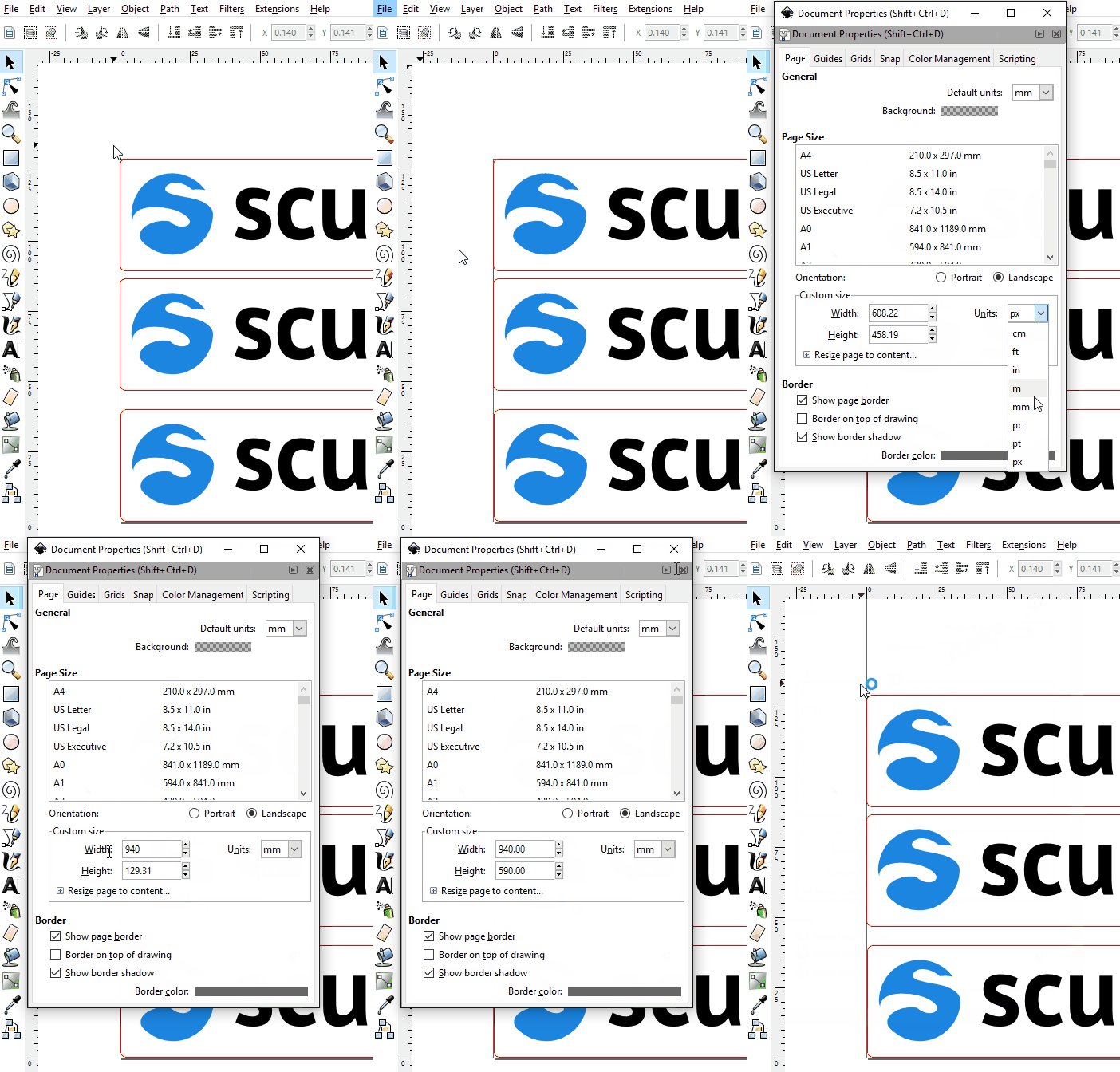
laser cutting inkscape page size.gif 

Generally, it’s a good idea during editing to set the page size to the maximum size Sculpteo can laser cut. We will change this later, but for now set the page units to mm and the page itself to a custom size of 940 x 590 mm, as this is the maximum size we can laser cut in one go. In this way we can see if we need to rearrange anything to make sure it fits in the laser cutter. Portrait or landscape is up to you, Sculpteo will adapt to fit your design in the right orientation in production.

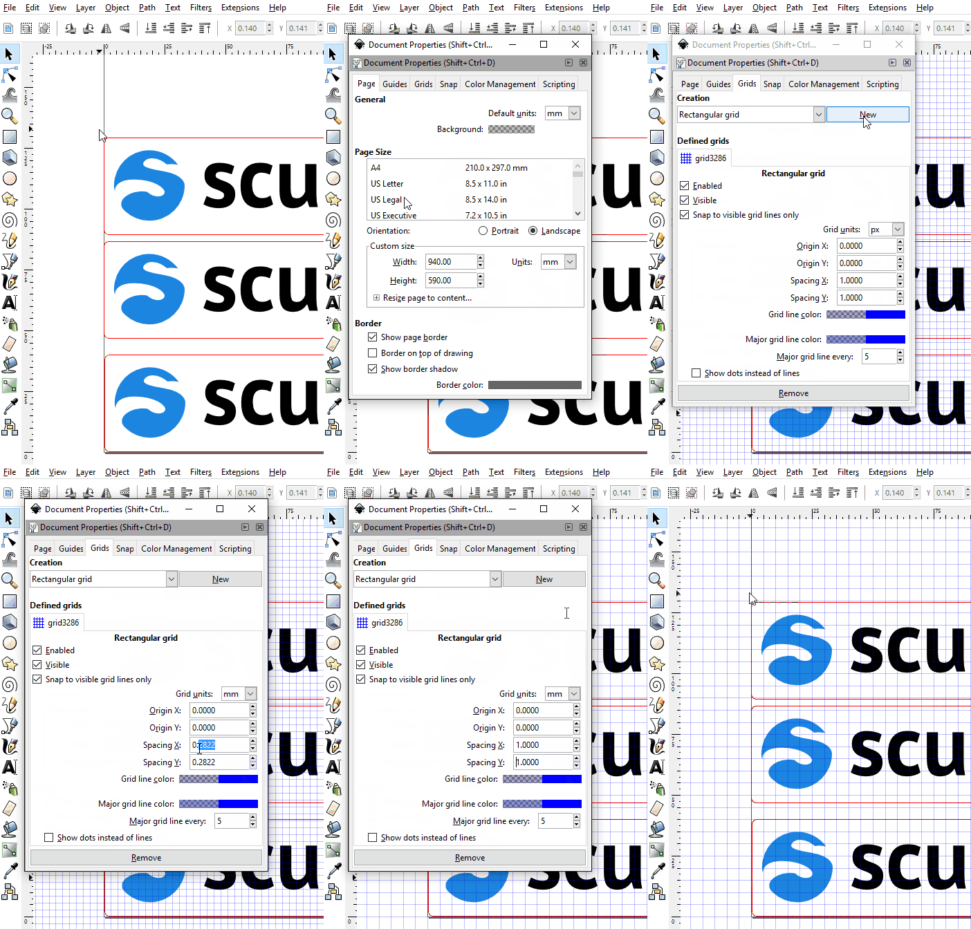
Laser cutting Inkscape Grid.gif 

By default the grid is not active, you need to create one, so while still in the Document Properties window, go to the “Grids” tab and create a new Rectangular grid. Set the grid units to “mm” with a spacing equivalent to the Minimum Safe Line Spacing for your chosen material. In our case, 3mm thick MDF, the minimum safe line spacing is 1mm

We have many other materials options that we don’t discuss in this tutorial. To read about them, and to make sure you respect the minimum safe line spacing for the material you’ve chosen, check our materials catalogue

Use whatever you prefer for major grid lines. This will let us check minimum spacing.

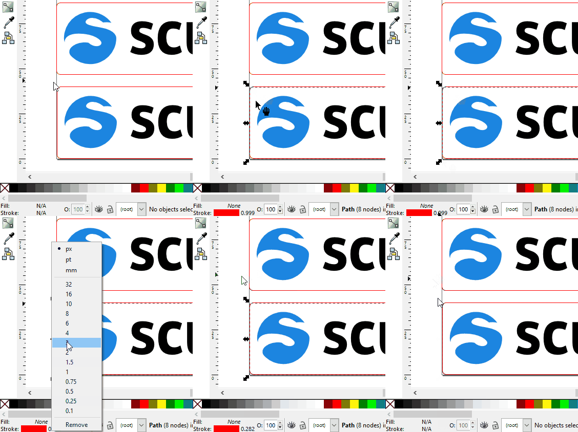
Laser cutting Inkscape Stroke Units.gif 

Back in your document (close the Document Properties window if it’s still open) you’ll see in the bottom left of the window two little entries that say “Fill” and “Stroke”. Stroke should have a number beside its color, which indicates its thickness (if not, you may have not selected an element – click once on any element in your design that has a stroke or outline). Right click on this number to see a list of available thicknesses and up top a list of available units. Choose “mm” so that our strokes all have their thicknesses measured in mm now. This will let us check any critical elements for kerf effects later on.