FreeCAD tutorial: 3D Modeling for 3D printing with FreeCAD

Summary​

1. Designing (modeling) for 3D printing

Designing for 3D printing implies to respect some design rules. Indeed, beyond the own limits to the materials used, it is necessary to keep in mind that the resulting file will not only be a virtual representation, but a support for the 3D printer to create a physical object. In this section, you will learn the key concepts of modeling with freeCAD for 3D printing. It’s important for the design to respect the following rules :
  • The different elements of your modeling should not intersect 
  • All the components you will design need to have a certain thickness. Freecad has no surface workbench, so this should not cause you problems.
  • Your part (object) must have an « inside» and an « outside». But we will see that Freecad manages that easily and automatically.
  • Your 3D file needs to be less than 50Mb after the export in .STL. This sizing is widely sufficient to generate a file without losing accuracy in the part. We will detail export possibilities and the file weight in the chapter dedicated to the model export.
  • Don’t forget that your file will become a real piece. In that way, you have to keep in mind the cantilever notions, the material thickness specifications, the minimum strength of materials of your part etc. We invite you to consult our page on materials.
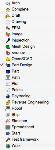
It’s possible to export different parts in one .STL file. However, it’s important to create as many different parts as different materials you will use for printing. The fans of Catia are never lost on FreeCAD, because the operating logic is the same. The set of tools is organized in workbenches allowing various operations.

1-workbench.jpg 

The detailed presentation of each workbench is available on Freecad website, but here we are focusing at two mains workbenches :
  • Part to work with CAD parts
  • Part Design to create part shapes out of sketches.

The volume modelling is used for simple geometries ( primitive objects like cone, box, cylinder…). To modify these geometries you have access to many tools like Boolean operations, fusion, common, cuts operations. It’s appropriate to create a part for each operation, in the aim to be able to make specific modifications on certain parts, with for example the Boolean operations. These operations can be used at any time of the modelling, even it’s easier and more logical to use it progressively. 

You can apply Boolean operations among all the created parts. 

To select it, go to the tab part > Boolean operations, otherwise just right click on the concerned part in the arborescence. For 3D printing application, the Boolean operations between two (or many) shapes will permit you to get one whole part. 

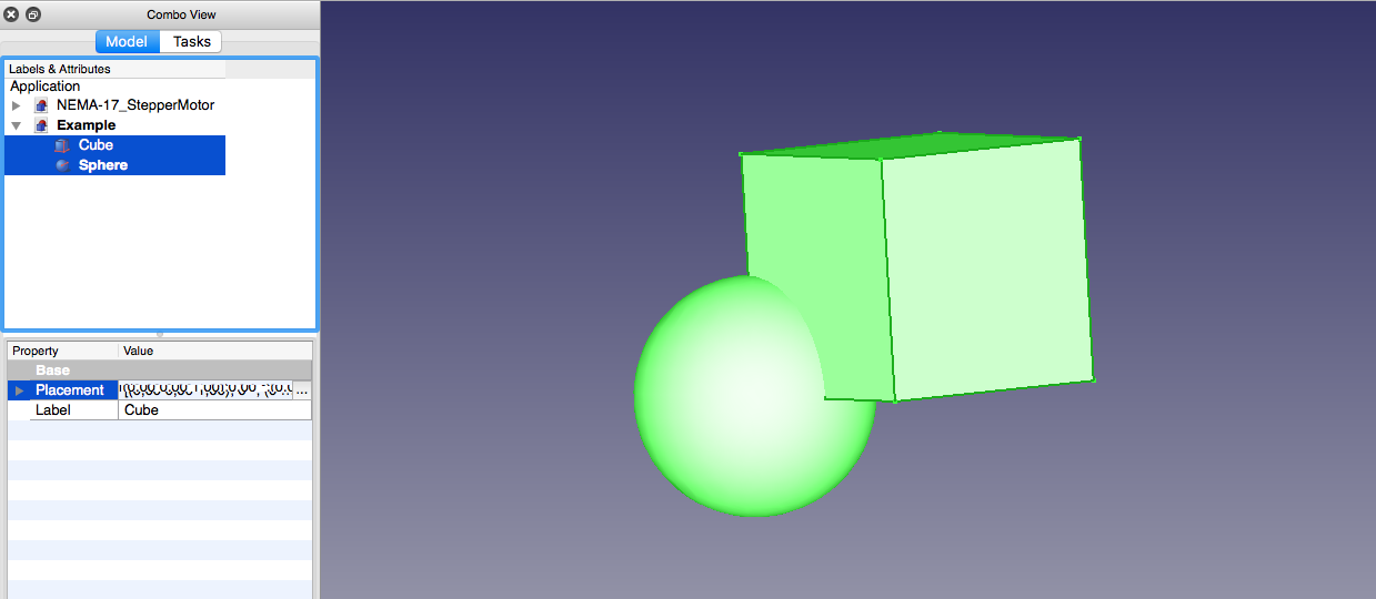
For that you just need to select two shapes : 

2-fusion.jpg

Then to apply one of the following Boolean operations : 

3-boolean.png 

Using the fusion function, the two parts merge into one new part. 

4-two parts.jpg 

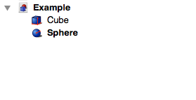
The new part is called by the operation name. Here, it’s called Fusion

5-one part.jpg 

FreeCAD is still under development, some features are still imperfect and Sometimes the Opencascade core on which turns freeCAD has trouble managing certain Boolean operations. 

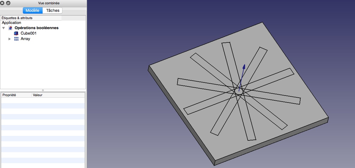
For example, a circular repetition patterns and a box: 

6-matrix .jpg

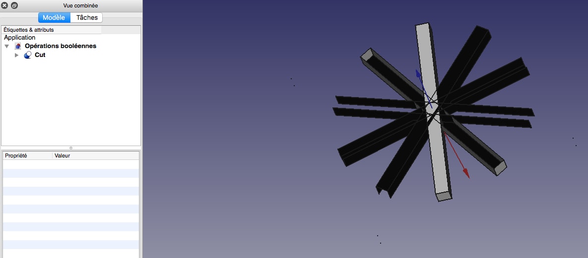
The subtraction of one to another makes a weird result, which is not exportable in .STL : 

7-not exportable.jpg

The solution to that issue is to use other parts (for example a cube rather than a matrix)

Another logic design is to draw a sketch in 2D and then into a volume. This is how Part Design workshop works.

Start by creating a sketch and select the plan in which you want to draw it:

8-sketch.jpg 

Then use the sketch tools : 

9-sketch tools.jpg 

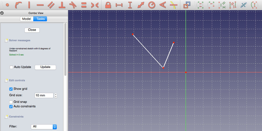
Freecad uses a system of constraints. Each item must have a unique position in the plan. Each point of the drawing can move in X and Y, so we say that a point has two degrees of freedom. A sketch featuring 3 points thus has 6 degrees of freedom, etc … 

10-sketch.jpg

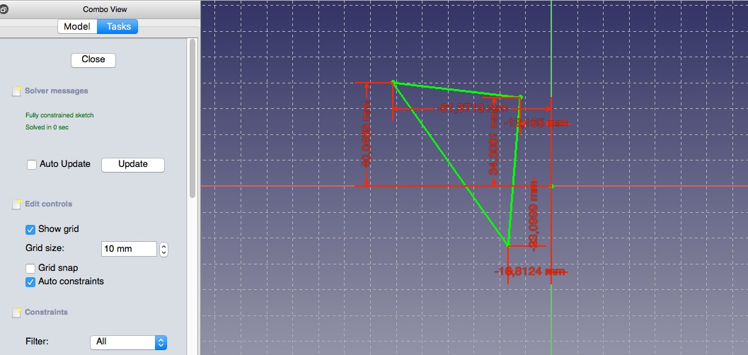
To avoid a sketch error during the transition to 3D, we need every point to have a specific position. Once the sketch is drawn you have to « force » each point. We therefore will use theconstraint tools :

11-constraint tools.jpg

Once each point is constrained, the outline turns green and the sketch is usable to create a 3D object. 

12-green .jpg

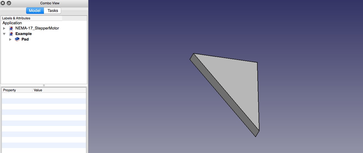
Then use the 3D tools to make a 3D object out of the sketch. 

13-3Dtools.jpg 

It is of course impossible to directly print an outline and that’s why this step is essential. 

14-volumic object.jpg


You get an object exportable in 3D. 

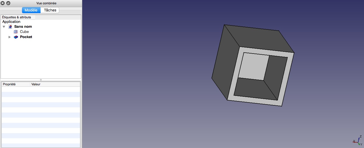
Hollow out a model is a common task in modeling for 3D printing. Indeed, it will help limiting the amount of material used, and thereby limit the cost of production. It is also essential for some materials (including ceramics) having an object based on a principle of constant thickness. To make your hollow model, you have several options. 

With the hollowing function, Sculpteo offers you to easily dig your model. Simply transfer your full file on our website and choose the location of holes for the drain (to evacuate the material present inside the object). The algorithm does the rest. 

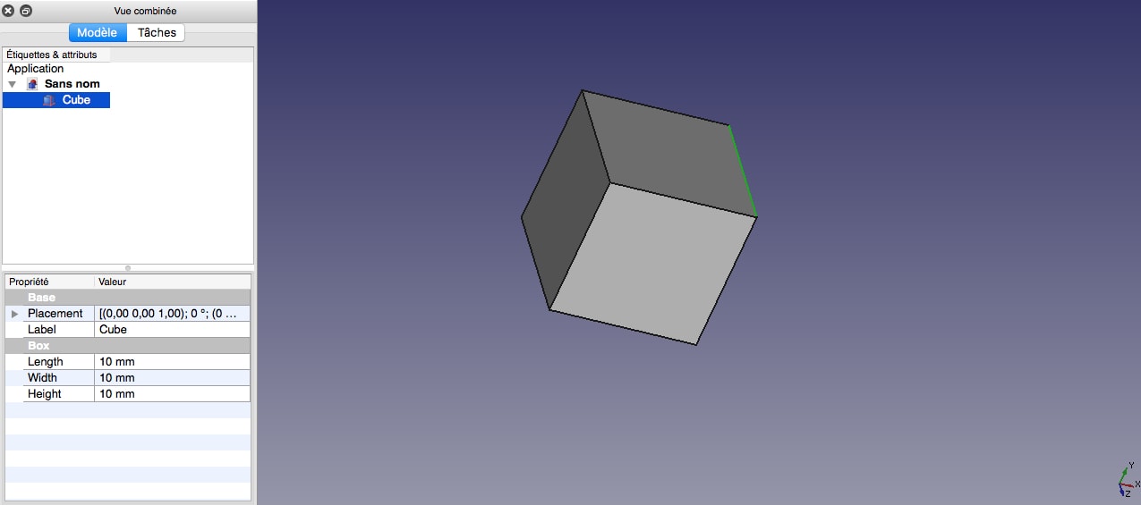
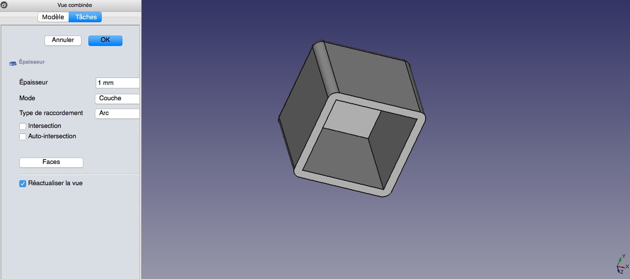
If you prefer your model scoop yourself, there is a “ thick” function in freeCAD share workshop.

15-thick.jpg 

Simply click on the opening side of the hull and choose the thickness. 

16-thickness1.jpg

17-thickness2.jpg

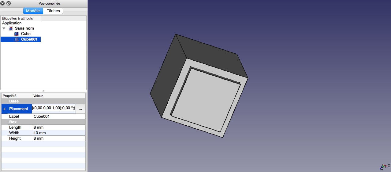
You can also use the standard functions of material removal. Boolean function as the “subtraction” in the studio “Part” 

18-part1.jpg

17-thickness2.jpg

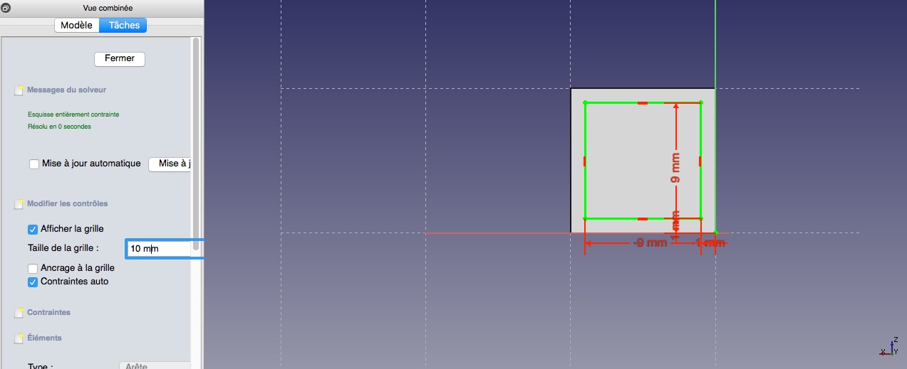
Or workshop material removal tool “Part Design” 

20-Part design1.jpg

21-Part design2.jpg


Warning: remember to always leave a hole for the discharge of the powder. 

Without drain holes, your object, even with the correct thickness, will be considered as full because the blocked powder inside can not be removed, however, its strength will be lower because it will be full of powder “ unfused “. Keep a drain hole is particularly important. For more information on the diameter of the holes to make, based on the material used, consult our page on materials

You can add text or raised patterns on your subject using the tools of Sculpteo but you can also do it in FreeCAD. Therefore you have two possibilities:

  • Using The Text tool in the workshop Draft freeCAD
  •  Import A .SVG file, for example logo

Use the Text tool in the workshop Draft

22-Draft tools.jpg 

The workshop Draft or drawing board is a workshop used to add basic features of 2D drawing to freeCAD. It can also manage the import of different vector formats like DXF or .SVG.

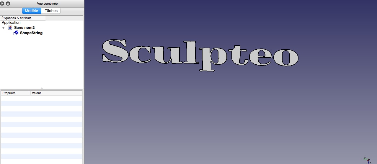
Use the text tool 24-Text.jpg (be careful, 23-Annotations.jpg only creates annotations unusable for a sketch to be extruded) to manipulate character strings from the font of your choice and make a usable3D sketch out of it.

Therefore you need to create a folder containing the fonts you want to .TTF format .OTF or PFB. 

25-Sculpteo.jpg

The resulting sketch is usable as any other sketch:

Sculpteo text.jpg


Import a .SVG

File Sometimes it can be useful to import a vector file without having to redraw it. This is the case when you import a logo for example. Freecad supports various vector formats DWG, DXF, etc.

Here we take the example of the .SVG which gives good results.

You can transform .PNG into .SVG with the drawing software illustrator, or thanks to an online service.

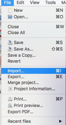
Click on File > Import 

27-import menu.jpg 

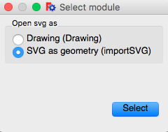
Then select import as geometry

28-import geometry.png 

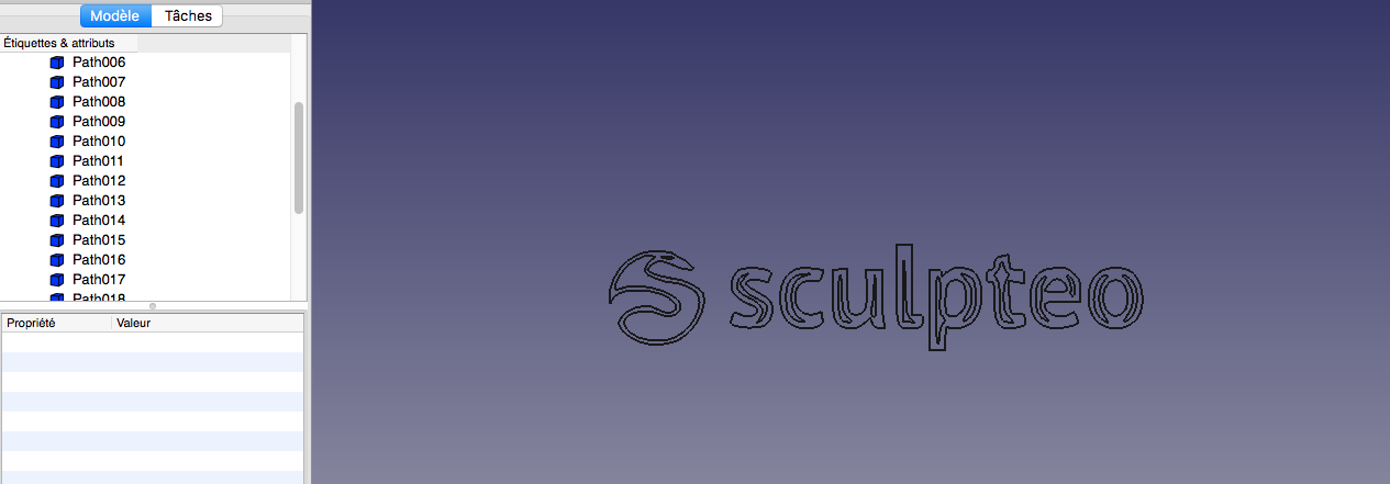
You get a set of paths

29-sculpteo.jpg

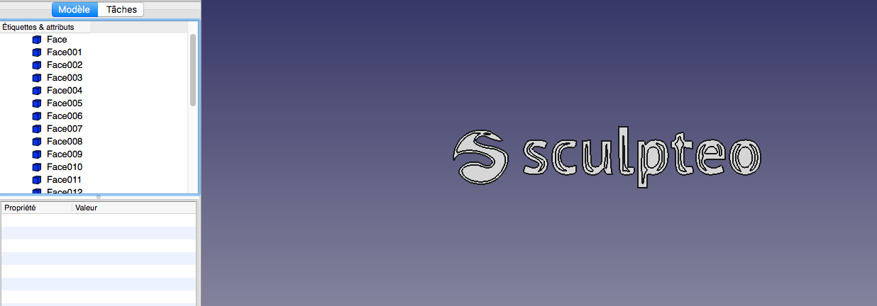
This path can not be used as such. For surfaces, you can use the tool level up

30-sculpteo.jpg

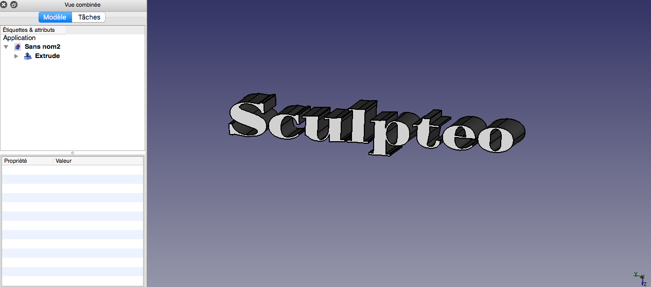
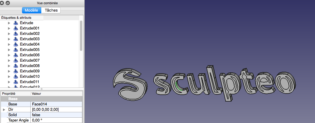
These surfaces are extrudable

31-sculpteo.jpg

With 3D printing, you can print the moving parts or objects articulated in a single printing. Your object is then build fully assembled, functional, and with non-removable parts. 

However, it must follow certain rules so that your object is functional. 

For example, for a plastic object, you must leave a minimum clearance of 0.5mm around the various bodies so that they are not merged during the printing. For the modeling rules based on materials, please visit our on materials. We will see how to measure elements and distances in the next chapter. 

To achieve separate elements of a specific distance, use the conventional constraints tools 

11-constraint tools.jpg

Freecad includes a materials management module, still very incomplete and only used for its integrated 3D rendering solution. However, the colors / materials information are not exportable. You can not export a file freeCAD including textures

Only a filter before exporting can exploit materials information by separating the file zones (each different material will be considered a different mesh area). You will need to export your freeCAD file using software to manage colors / textures (like Blender for example), assign your textures in this software, and then export it again. 

This process is particularly laborious and involves many risks of failures, during the export of materials and during the export of volume. 

That’s why if the texture is important for your modeling work, you’ll have to carry directly the model into a software manager textures, like Blender

Moreover, UV management is almost impossible with freeCAD. The basic UV are unusable and unfold a mesh exported freeCAD file is often a challenge that will waste more time than it will save it. 

For more information on modeling for 3D printing with Blender, please consult our tutorial Prepare your file for 3D printing with Blender.