Fusion 360 Laser Cutting Tutorial: Create a sketch for Laser Cutting

Summary​

1. Fusion 360 Laser Cutting Tutorial: Create a sketch for Laser Cutting

To get started, this is the interface that appears when you open the Fusion 360 software.

Webp.net-resizeimage (1)_3reXnQu.jpg
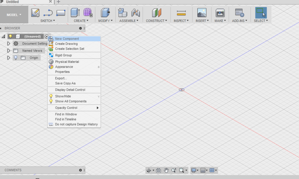
First thing, right click on the “unsaved” button to create a new component, as shown in the following image:

Webp.net-resizeimage_96xVeXc.png
It is recommended that each time you add a new sketch you rename it so you don’t mix things up when your design gets more complicated.

Webp.net-resizeimage (1)_krAW4QL.png

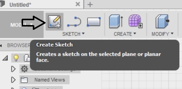
Now, let the drawing begin! We will start by creating a plane sketch selecting the icon with the pencil as shown below.

5_omQOMg8.jpg
Make sure to turn on the origins to keep everything aligned. To do so, click on the yellow bulb icon on the left side.

6_7ffHekl.jpg

Next step is to create a draft shape of the base of the pencil case we want to create. 

This step is to give an approximate representation of the drawing, so don’t bother to be very precise regarding dimensions. 

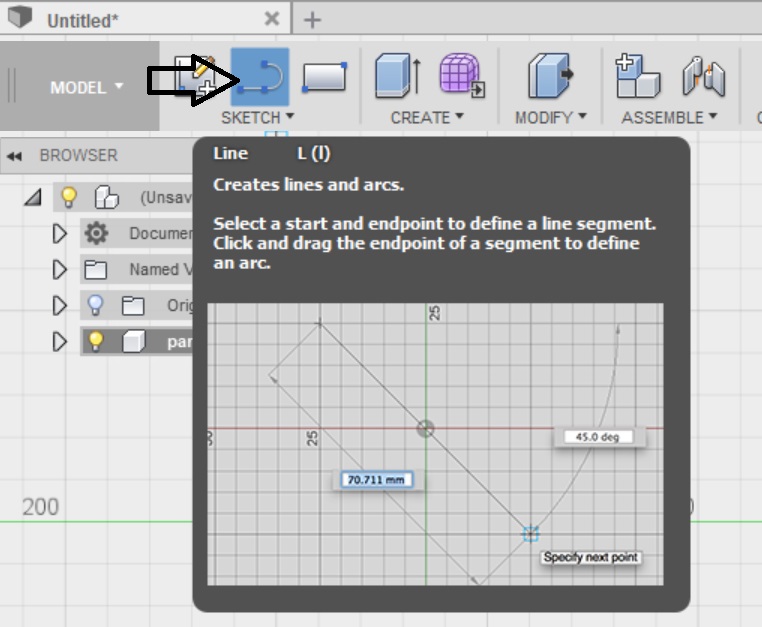
Click on the “sketch” button.

6_OyEvozL.jpg

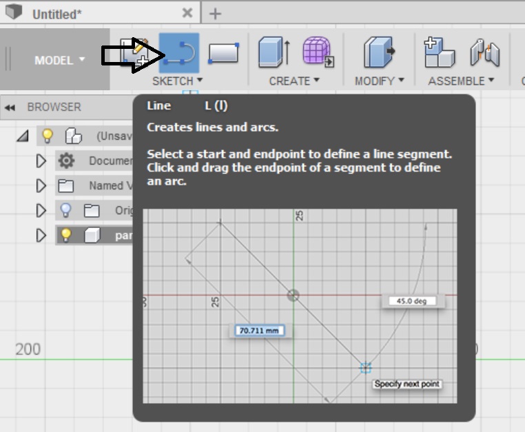
Let’s start by creating continuous lines to create the outline of the sketch.

Webp.net-resizeimage (3)_pfj2ddB.jpg


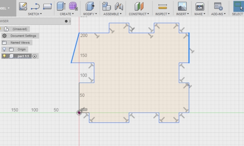
Once you are done with the first draft of the sketch, press enter to exit the sketching mode. In this step, the draft sketch looks like this:

Webp.net-resizeimage (4)_NbZ0pMs.jpg

In order to convert this draft into the final sketch, we have to apply on it some constraints. It is important to apply constraints to the sketch so that its analogies are locked down. Otherwise the sketch will have a free form that will be affected every time we set a new dimension and the whole design will be changing accordingly.

In this case, the two highlighted lines should be parallel, as the sketch should be symmetrical. So, we have to add the constraint of the parallelism. To do that, select the lines by holding pressed the “Ctrl” button

Webp.net-resizeimage_LU7OQY8.jpg
To add the constraint, go on the hidden bar on the right of the board, and select “parallel”.

Webp.net-resizeimage (1)_f64XCJK.jpg
 Once you click on parallel, the constraint is applied and the sketch looks like this:

Webp.net-resizeimage (2)_NrJI3jW.jpg

Keep adding constraints to all the lines that should be parallel with each other so that you lock the form of the sketch down and eliminate the degrees of freedom in your design.

Once the constraints are applied, it’s time to add some dimensions to lock everything down. To do that, select the line on which you want to apply the dimension and go to the “sketch” tool. From there, select “Sketch Dimension” as shown in the image below:

Webp.net-resizeimage (3)_Hv83npU.jpg
Now it is possible to add the value of the desired dimension in the box that appears next to the dimension line. Repeat that for all the lines for which you want to define dimensions.

Webp.net-resizeimage (4)_Ecksjrx.jpg

In the end, the sketch should look like this:

Webp.net-resizeimage (5)_oI2V32R.jpg

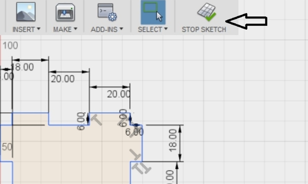
Now that the constraints and the dimensions are set, the sketch is completed. To exit the sketch area and move to the next steps, select the “stop sketch button”.

Webp.net-resizeimage_h1gqSJe.jpg

After that, the sketch should look like this: 

Webp.net-resizeimage (1)_ngdllYo.jpg

Right now the sketch is in 2D. In order to visualize it in the 3D space, we need to add some thickness to it. Let’s add a parameter defining the thickness of our part. Adding parameters is a smart way to define the current thickness of your sketch. If you want to change the thickness of your parts later, you can modify the value of the parameter and it will change automatically.

Moreover, if your sketch contains multiple parts, you can use the parameters you set once for all the parts that you will design for now on.

So, this is a convenient and automatic procedure that makes the designing process less complicated. 

To add parameters, go to the “Modify” tool, and select “Change Parameters”.

Webp.net-resizeimage (2)_M4ncYrq.jpg

A window will appear, asking you to define your parameter.

Webp.net-resizeimage (3)_OzIFyaT.jpg

Let’s name this parameter “thickness” and set it at 2.5 mm. We set this value because this is the thickness of the laser cutting material we will use for producing the part.

Webp.net-resizeimage (4)_iCCgJeS.jpg

To apply the thickness parameter, you have to extrude your sketch. To do that, go to the “Create” button and select “Extrude”.

Webp.net-resizeimage (5)_eDziyKq.jpg

Webp.net-resizeimage (6)_djFEoDN.jpg

You will be asked to define the value of the extrusion.

Webp.net-resizeimage (7)_GiMFBS2.jpg

Since the thickness parameter was added at the previous step, instead of a number you can type “thickness”. It is automatically recognised that the value of the thickness is 2.5. 

If you want to change this value, you can do it by editing directly the parameter itself.

Webp.net-resizeimage (8)_YJt7pgy.jpg

Now the 3D sketch should look like this: 

Webp.net-resizeimage (9)_var0ohU.jpg