Despite the fact that SolidWorks does not directly create a mesh, it is still able to produce one during the export, and that type of file is particularly useful for 3D printing. Mesh files are the most common type of files used with 3D printing. Particularly .stl files is a filetype that SolidWorks has the ability to export directly in to.
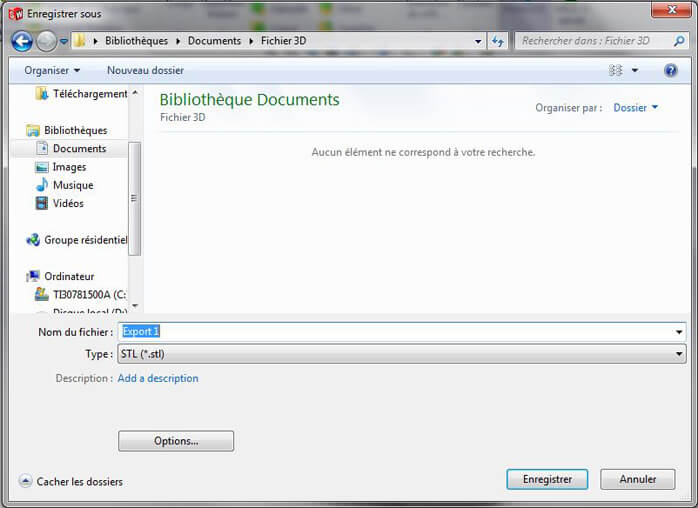
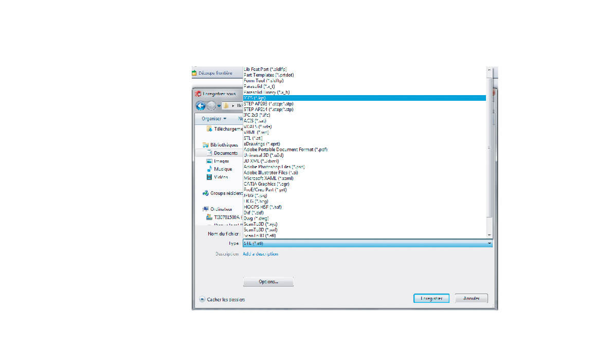
To export your model select “Save as…” and select .stl under “Type”.
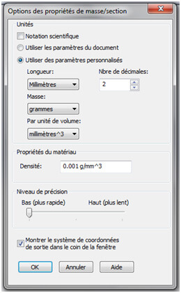
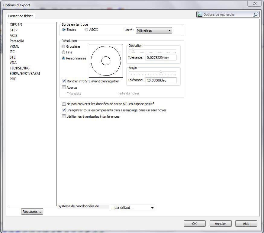
Before clicking save you can refine the default options if you’d like further precision.
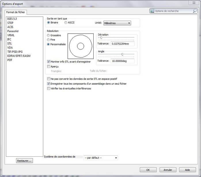
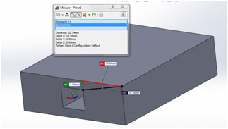
The two characteristics that greatly affect the precision of your model are the deviation and the angle. These characteristics determine the angles and distances that SolidWorks will generate for the triangles that will make up the object’s mesh.
The “Fine” level of precision is usually acceptable, though you are able to define that yourself. Note: keep in mind that the printers themselves have an accuracy of up to .01mm so anything smaller than that will not be regarded. Not to mention the smaller that specific number, the larger the file will be.
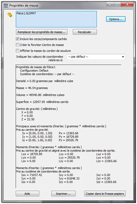
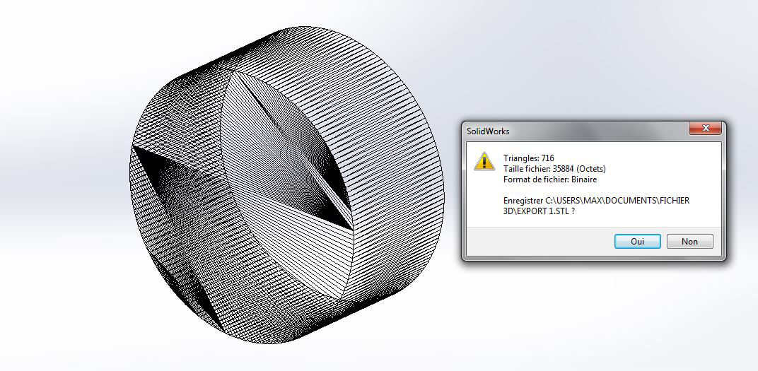
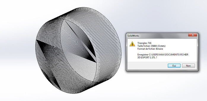
Also, before the final export, SolidWorks will show you a final rendering of the mesh, an estimation of the file size and the number of faces it will create. The estimated file size will give you an indication as to whether or not the file can be uploaded.
These precision parameters must be adjusted according to the final size of the folder and of the object you plan on printing. It is quite rare to create an object that requires anything less than .05 mm or that an angle will need to be less than 2 degrees.
To give you an example, if you’re looking to create a cylinder and you define a level of precision of .5 degrees, your cylinder will be defined by 720 edges when a circle only has 360 degrees. If a cylinder is 5 cm in diameter, the differences in edges would be invisible to the naked eye.
Particular Case: Multiple Bodies and Assemblies
There are a couple of export possibilities if you are working with SolidWorks for a piece that will be assembled. You can, under the “Options” menu choose to save the model in a singular .stl file, which will place all of the moving pieces in a single file, otherwise they will each have their own .stl file.
Some files would be too large and precise to exported in a single .stl file. If that is the case you must re-adjust the particular precision values. If this still does not produce the required result, or if too much precision is lost, it may be preferable to export in a vectorial format which is based off of a system of nurbs (similar to SolidWorks) not a mesh. The Sculpteo website is also able to accept the vectorial formats .iges or .step.
 Connect with Google
 Connect with Facebook