Slicer for Autodesk Fusion 360 Tutorial: Slice your 3D model

Summary​

1. Laser Cutting with Slicer for Fusion 360:Slice your 3D model

There are two possible ways you can get started with this “Slicer for Fusion 360” tutorial. 

One way is to import your 3D file directly to the software. 

The other way, is to import your 3D model to the “Fusion for 360” software, and from there to export it to “Slicer for 360” software. This is possible because, as stated at the beginning of this tutorial, “Slicer for Fusion 360” can be used as an add-in for “Fusion 360”. 

In this tutorial, we will use the second way.

So, let’s get started! 

First, we will open the 3D model in “Fusion 360” software. In our case, the 3D model is a dragon, saved in .stl format.

 Webp.net-resizeimage (3)_i4ZuWoT.jpg

Once imported in the software, the 3D model is set automatically in “SCULPT” mode as you can see on the upper left icon. You have to change this setting to “MODEL” mode.

Webp.net-resizeimage (4)_Ha2aI1A.jpg 

Once you get the final shape of you 3D model, go to “MAKE” and select “Slicer for Fusion 360”, as indicated by the arrows in the following picture. 

Webp.net-resizeimage (5)_GmWKK2c.jpg 

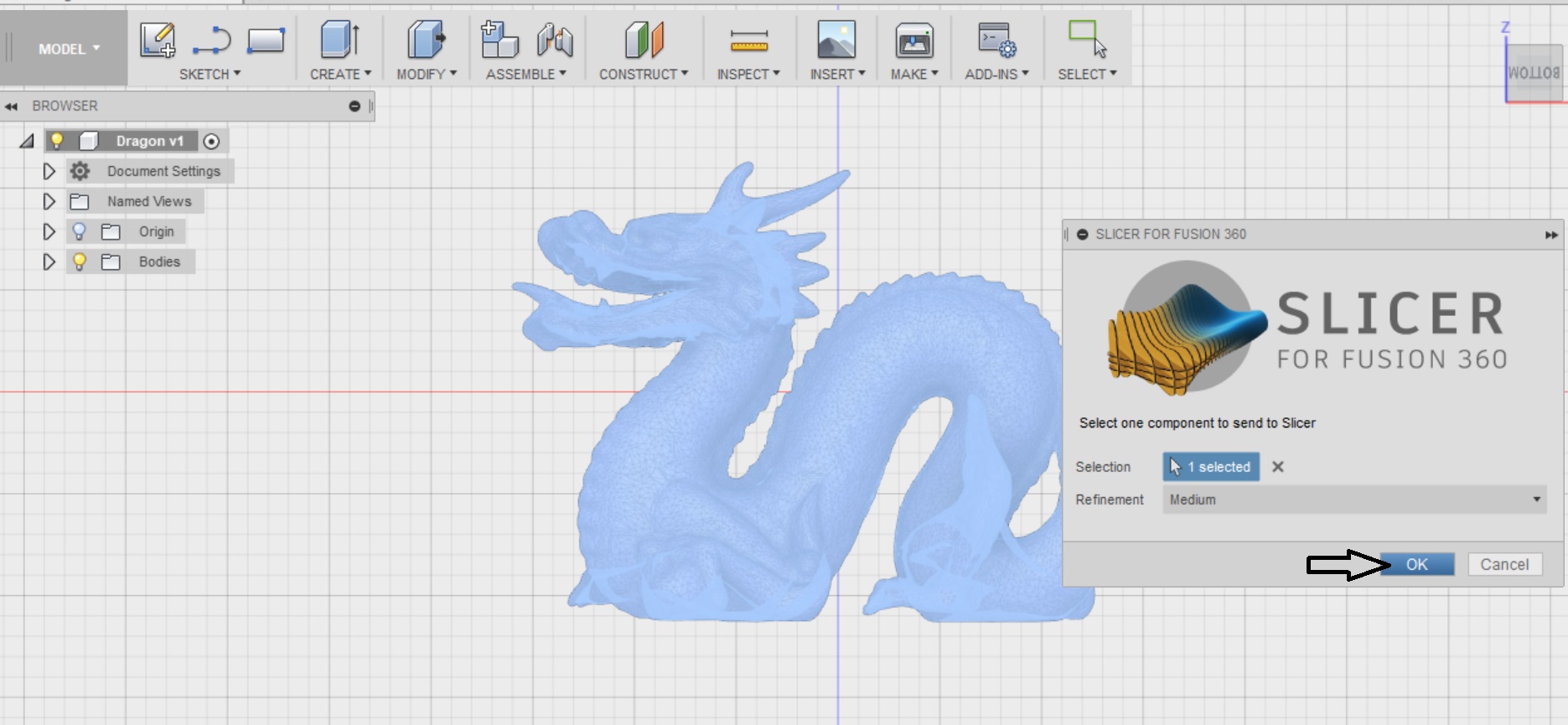
Then, a box will appear, asking you to select the items that you want to export to the “Slicer for Fusion 360” software. Select your 3D model to turn it blue, and then press “OK”.

4_YCTWERD.jpg 

Now, the 3D model is automatically transferred to “Slicer for Fusion 360”. The interface of the software should look like this: 

Webp.net-resizeimage (6)_pbYw76O.jpg 

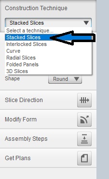
Notice that on the left side of your screen there are the “construction techniques” (or in other words the “slicing techniques”) that the software offers. As you can see, there are 6 slicing modes that are available in the software. Each mode slices your 3D model in a different way, so you have to experiment with some of them to see their potential. 

6_CGnfnP6.jpg 

Let’s begin with the “Stacked Slices” technique. 

Once you select this mode, the 3D model is sliced like this:

Webp.net-resizeimage (7)_dOkiUXK.jpg 

This mode enables you to see how the 3D model looks like when it is sliced in layers that are placed one next to the other. You can rotate the 3D model to get its full preview by selecting the “360° preview” button.

Webp.net-resizeimage (8)_JGCLtWo.jpg 

Alternatively, right click on your mouse and move the 3D model around. 

Let’s try another slicing technique. 

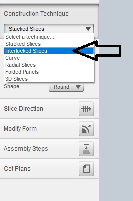
Select the “Interlocked Slices” mode from the menu on the left side.
11_WnyYdZg.jpg 

Now the 3D model has a totally different slicing appearance than before. 

Webp.net-resizeimage (3)_qz7T1hQ.jpg 

As you can see, this construction technique lays the layers in a very different way. The sliced 3D model consists of both horizontal and vertical layers, that are connected to each other.

Let’s experiment with the options that are on the left side of the menu. 

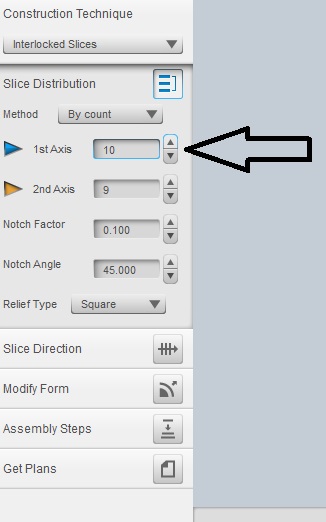
For example, let’s change the value of the “1st axis” option.
13_PNhJ2ON.jpg 

We notice that the higher we set the value of the “1st axis” option, the more layers of our model. Obviously, this change affects also the number of parts of the sliced model, and consequently the number of sheets that will be used for laser cutting. You can see this on the right side of the menu where the plans are.

Webp.net-resizeimage (4)_mkXIRJb.jpgWebp.net-resizeimage (5)_sXLMG1g.jpg

We get the same effect if we change the value of the “2nd axis”. Indeed, the higher the value of the 2nd axis, the more layers our 3D model has. 

Webp.net-resizeimage (6)_4MBOAlg.jpgWebp.net-resizeimage (7)_bTsN9vJ.jpg

To sum it up, if you want a more detailed representation of your 3D model, you have to add more parts to it. In order to do that, you have to increase both values of the the “1st axis” and the “2nd axis” that are on the left side of the menu. 

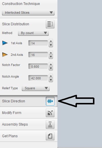
Moreover, if you select the “Slice Direction” you can affect the way that the 3D model is sliced.
INTERLOCKED.jpg 

Move the orange axis of 90 degrees and you will get a totally different orientation of the horizontal layers. The 3D model should look like this:

Webp.net-resizeimage (8)_UTvHOFa.jpgWebp.net-resizeimage (9)_88amOyE.jpg

“Curves” is a great construction mode that “Slicer for Fusion 360” software provides. This mode, enables you to adjust the final shape of your sliced 3D model. Let’s see step by step what it means.

First of all, let’s see how our 3D sliced dragon looks like before editing its parameters in the “Curve” mode:  

Webp.net-resizeimage (10)_GB1Z3mP.jpg 

Now, select the “Slice Direction” button. An orange line with blue dots. This is the curve of the 3D model, and the blue dots are the parameters that you can modify to change the curve. 

Webp.net-resizeimage (11)_8CRSDQk.jpg 

Click on one of the blue dots and drag it down. Drag and pull the curve in any direction you want and you will notice that the orientation of some layers changes. 

Webp.net-resizeimage (13)_6LGQOYI.jpg 

By modifying the original curve of the 3D model, you modify the direction of all the layers that slice the model. Consequently, you significantly modify the way the layers are connected with each other.

Webp.net-resizeimage (12)_1QHhsSq.jpg 

Now your sliced 3D model has a totally different appearance.

Now let’s see another slicing technique, the “Radial Slices” one. As you can understand by the name itself, the sliced parts are laid down in a radial construction. The 3D model should look like this: 

Webp.net-resizeimage (3)_E2uz9gN.jpg 

If we modify the value of the 1st axis, only the vertical slices are affected. The higher the value, the more dense the layers will be.

Webp.net-resizeimage (4)_SqWX1cv.jpgWebp.net-resizeimage (5)_ctNBVnL.jpg

In order to change the “radial slices”, we have to edit the “Radial (COUNT)” value, as indicated in the following pictures.

Webp.net-resizeimage (6)_CPr0Lnm.jpgWebp.net-resizeimage (7)_Px9V3Xq.jpg

As expected, the higher the value, the more slices your 3D model will have. 

Moreover, check out the plans that are on the right side of the screen. By increasing the value of the radial slices, the final construction is made of more parts.

This slicing technique, gives your 3D object an origami look. The plans on the right side of the menu show the unfolded parts of the model. Once these parts are laser cut, you can fold them and assemble them together to get the final shape of the model. 

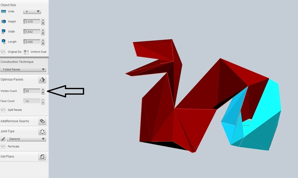
Let’s see the parameters of the “Folded Panels” technique. First of all, we will check out the “Vertex Count” mode.

The higher the value of the vertex count, the more detailed the representation of the actual 3D model will be. The pictures below demonstrate the differences between a low-value vertex mode and a high-value vertex mode.

Webp.net-resizeimage (8)_PF8AMar.jpgWebp.net-resizeimage.jpg

Webp.net-resizeimage.jpgWebp.net-resizeimage (11)_5lpomK8.jpg

As you probably have noticed, this was the representation of the 3D model in the “Diamond” mode, selected under the “Joint Type”. 

34_37CRV01.jpg 

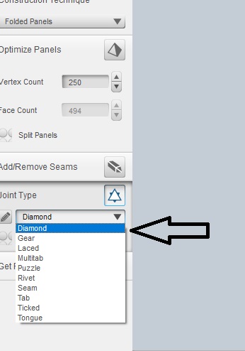
If you select other modes of “Joint Type”, the representation of the sliced 3D model, will be different. In addition, the plans and the shape of the parts shown on the right side of the screen will be different too. For example, the “Gear” or “River” mode, give a totally different result:

Webp.net-resizeimage (12)_Lw5Z6R0.jpgWebp.net-resizeimage (13)_kkaX0cq.jpg