There are several reasons why digital models for 3D printing should be hollowed but the main one regards the amount of material used to produce it. In 3D printing, unlike common production techniques, the cost to fabricate an object is not dictated by its shape complexity, but mainly by the amount of material that it requires. Making your object hollow will then strongly affect your product costs, sometimes decreasing it by up to 60 or 70%.
Another important reason to hollow your model is to keep your product lightweight if that’s a factor you are aiming for.
But just hollowing your model doesn’t affect your product if your hollowed part is not connected to the outside through at least two holes. The reason is related to the technology: “unprinted” material would be trapped inside your model with no way for it to escape.
Sculpteo has released a fabulous hollowing feature that allows you to do this operation online, simply by choosing the position of the holes on your model. You can upload your 3D file and try it now.
In many examples of successful 3D printed products, we have seen designers taking advantage of this production driven restriction, creating patterns of cavities along the whole model surface. This confers aesthetic factors while reducing the amount of material and therefore the costs of the product. How can this be achieved with Inventor?
We are creating a simple cube (Primitive Box) and choosing one of its faces as 2D Sketch plane (  ).
).


Then press the ‘Insert AutoCAD File’ button (  ) to import the vectorial drawing you want to use as a cutting pattern on the surface (You can also import other types of files or draw something directly on the sketch plane).
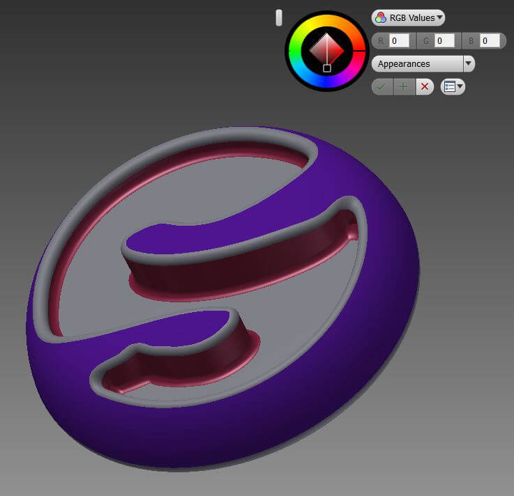
We’ve uploaded the Sculpteo logo, then scaled it (  ) and moved it (
  ) to the center of the surface.

Then what we need to do is to use the command ‘Project to 3D Sketch’ (  ) and select the surface on which the sketch is lying. Press OK and exit the sketch (
  ).
).
We are then able to separate the area of the logo from the rest of the surface through the feature ‘Split’. Select the 3D Sketch just created with the ‘Split Tool’ and the surface which it belongs to as ‘Faces’. Press ‘Apply’.

The final step is to use the feature ‘Shell’ to hollow the model, removing the logo’s surface just created.
Pick the ‘Shell’ feature (  ) and select the face to remove. Deselect ‘automatic face chain’ if this face belongs to a bigger surface as in this case, and choose the wall thickness you want to achieve, depending on the material. For instance, Plastic material needs to be at least 0.8 mm and 2 mm to be considered as rigid. You can find more information about material specifications on our Materials page.
Now you can press ‘Apply’ to hollow the model, and engrave the logo.

 Connect with Google
 Connect with Facebook


 Cut or
 ).
).


 ) you can trace two consecutive oblique faces of the thread and connect their middle points. Use the tool ‘Dimension’ (
 ) to measure the length of this line, and if it corresponds to your thread Pitch, it means you’ve modeled correctly. If what you want to measure is the distance or the angle between edges, points or faces of the model, or check the size of areas and loops of the faces, you should then access the features called ‘Measure’ under the ‘Inspect’ panel.

 ) tool, selecting two opposite faces of a wall, and read their distance (Wall thickness) in the active window.